Covering a time of roughly 6000 years.
By Robert Steven Diamond and Brian Garret Kassel
Brooklyn Historical Railway Association
Columbia University
Abstract
Generally hidden from public view, out of our daily thoughts, and literally under our feet, are myriad urban underground tunnels that make our modern megacities possible. From their ancient beginnings in antiquity, as a means of supplying fresh water and draining waste water from cities, underground tunnels evolved into a means of providing high capacity rail mass transit in our most densely populated urban centers. This paper provides a broad overview of the evolution of urban tunnels across a 6000 year time span and includes the specific engineering formulas/computations for the earliest 19th century subways/infrastructure projects based on the Roman vaulted arch tunnel.
Introduction
One of the problems of correctly interpreting history is that the original meanings of words and phrases are sometimes lost, or at least distorted. For example, the New York word “subway1” is a contraction of a two-word phrase: “Subterranean passageway”. Linguistic terms, like technology itself, do not arise within a vacuum; there is always something similar that came before2.
We now present a brief outline on the evolution of the “Subway”, or “Underground Passageway”, covering a time of roughly 6000 years. We will discuss ancient sewers and aqueducts; these were big enough people to walk through and often served as unplanned pedestrian tunnels. This paper begins chronologically with the ancient sewers of Mesopotamia, and then proceeds to Jerusalem, Greece and Rome. We will also discuss the Subway’s most direct from the Ancient world: The Roman Cryptoporticus (vaulted underground passageway used by vehicles and pedestrians), before progressing to 19th century urban underground railway tunnels (including the first subway lines constructed in Brooklyn, NY and London, UK).
Ancient Underground Sewers and Aqueducts
Overview
As ancient humans transitioned to living in urban communities of high population densities, the need arose for subterranean urban infrastructure. In ancient cities, like our modern ones, there is a need for water piping, drainage and sanitary sewers.
The Earliest Known Urban Underground Tunnels-the Subterranean Sewers of Mesopotamia
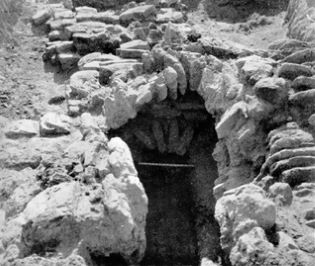
Technique in Antiquity” gives us perhaps the most technically detailed description of the earliest known urban underground passageways and similar ancient structures4. In regards the Mesopotamia, he states: “Babylon was in possession of very big watering sewers, that the private houses were connected via by-pass channels with the main sewers. In Nimrud, [the researcher Layard] discovered a vaulted, pointed arched drainpipe beneath a building.” [4] This vault was described as constructed of ‘burnt brick’ (fired brick), with these bricks covering the floor and arched portion of this drainpipe. The brick was rectangular5. [4] Merkel further describes these structures:
Vertical stand-pipes are discharged into this by-pass channel. They were used to discharge the waters into the drainpipe. Beneath the north-western palace in Nimrud, Layard discovered also a vaulted drainpipe. Beneath the road pavement of the ruins of the elder Palace in Nimrud several quadrangular drainpipes, made of [fired brick], led into different parts of this building. Round pipes, ending in a perforated plaster plate and normally situated in a corner, were connecting the drainpipes with those floors in different rooms which had to be drained. All junctions were united in a main sewer, and this one was emptied in the river [4] .
Elsewhere in Mesopotamia, in Bagdad, there is another remaining relic from Babylonian times: “the ruins of an imposing drainage ditch. A subterranean channel, made out of big quadrangular brick, and connected with the name of ‘Nebudkadnezar’” [4] .
The Earliest Known Urban Underground Infrastructure (the Subterranean Sewers & Evolving Aqueducts of Jerusalem 2600BCE-586BCE)
In Jerusalem, portions of that city’s ancient sewer systems have been preserved. Many have been found through archeological escalation:
“Schlick discovered a pipe, big enough for a man to enter, just a few meters beneath the soil. This channel is 60 cm wide and ca. 2 meters high. Initially, it was equipped with a vaulted ceiling. This ceiling was composed of just a few worked stones; later, it was covered with bit flat stones. The channel leads towards the Kidron Valley, the outlet is blocked. The purpose of this channel was, obviously, to discharge the brackish sewers from the north-eastern part of the city. Schlick writes the following words about the sewer conditions during the old times of Jerusalem, before King David invaded the city: “… the main sewer which came from the North, from Millo, was comparatively more spacious and more in a linear slope than the many short by-pass channels branching off to the left or to the right. Naturally, the outlets of these channels at the edge of the
rocket were lower than the alley and the houses. But Joab entered Jerusalem through these channels, and David came into the possession of this City, without any bloodshed.” [4]
The passage above conveys the importance of tunnels, how cities thrived (and were sometimes even conquered) using these man-made urban underground passageways.
“During the middle bronze age (2200-1550BC) springs were included within the walls of cities…. the most complex water system from this period was discovered in Jerusalem. It includes a tunnel that brought water from the Gihon Spring to a pool protected by a massive fortress.” [5]
According to the Associated Press, one Jerusalem tunnel that may have been used by David’s men was a water tunnel whose construction date was 1800B.C.: “The water system seems to have been abandoned in the late eighth century B.C., when the 1800-foot Hezekiah’s Tunnel was dug to carry water from the spring to a protected spot on the western side of Jerusalem.” [6]
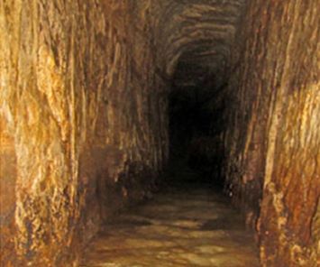
As shown in Figure 2, Jerusalem was also a pioneer in aqueduct design during the Iron Age (1000-586BC). During this period “complicated and impressive water systems were found in [Jerusalem]… The main achievement of this period was to bring external water, from springs or runoff, into the city. This required exceptional engineering capability$” [5] .
The Earliest Known Urban Underground Passageways & Subterranean Canalization (Cloaca Maxima “The Great Sewer”, Ancient Rome)
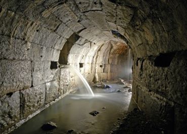
The best known ancient large scale urban underground tunnel system is Rome’s Cloaca Maxima (The Great Sewer) [7] [8] . This drainage system was originally built for transporting flood waters and land reclamation purposes (draining a swamp) [10] . The Cloaca predates Rome’s famous aqueducts. It predates even the Roman Empire (and the Roman Republic that preceded the Empire). As shown in Figure 3, this engineering marvel is still used by the current day inhabitants of Rome. Impressively, the Cloaca is still functioning as designed, even after more than 2-1/2 Millenniums of continual use [10] .
The Cloaca was also the start of the “cut and cover” underground tunneling practices in urban environments6. Vitruvius, sometimes referred to as the world’s first known engineer, wrote of the “cut and cover” method in his 1st century BC work: “The Ten Books on Architecture, Book VIII, chapter VI”. He states: “Parietes cum camera in specu struanter”. In English: “If the tunnel [specus] was driven through… earth or sand, there must be massive vaulted arch [4] [11] . A cut and cover method and vaulted arch construction (based upon roman designs) was utilized in many 19th century Infrastructure projects (ex. train tunnels, aqueducts, etc.,)―projects which we will discuss in detail later in this paper.
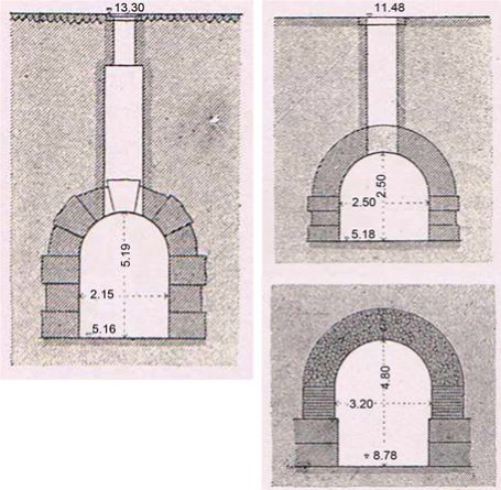

In Figure 4 and Figure 5, Merckel provides the technical details of the Cloaca Maxima7:
This structure is approximately 531 meters (1742 feet) in length [4] , with a typical cross section of roughly 9 ft × 12 ft [4] . The Cloaca was built by two Etruscan Kings of Rome. Construction is believed to have started about 600BC, and to have been completed sometime around 500BC, after a long political delay8. The Cloaca Maxima is also said to have been “the earliest application of the arch [vault] in Rome” [12] .
The Cloacea was a great public work. Great infrastructure projects form the spine and skeletal system from which a city springs forth up from and around. The Cloacae defined Rome, it defined it shape and boundaries.
“Jordan holds the view that by building the Cloaca and erecting the surrounding wall… [that] Rome received its’ specific imprint. The surrounding wall with all its’ gates was for centuries the boundary of the City of Rome; it established the major traffic routes. The Cloaca Maxima enabled the agricultural cultivation of the plains between the hills and the river. Presumably, most of the Cloaca was uncovered in the beginning, at least a great deal of it.” [4]
Executing such a large construction undertaking with nothing more than human labor and hand tools, must have been an extremely formidable and unpleasant task:
Brutus [founder of the Roman Republic, speaks to] the people of Rome after the expulsion of the royal house [509BC], …these words, which plainly refer to the Cloacae: “He compelled you like slaves to lead a miserable life, hewing stone, cutting wood, carrying enormous loads, and passing your lives underground.”9 From Brutus’s statement we can deduce that the construction of the Cloacae involved great human sacrifice.
“According to Pliny the Elder, writing sometime around 77C.E., many of the workers resorted to suicide to escape the long, hard, grueling labor―but Pliny also seemed to think the loss was worth it. “The ground is shaken by earth tremors; but in spite of all, for 700 years from the time of Tarquinius Priscus, the channels have remained well-nigh impregnable.” [10]
Writing more than 18 centuries after Pliney the Elder, the historian Dennie reaches a similar conclusion: “Nevertheless, it is certainly true that no public work ever done in Rome surpasses in utility the Tarquinian sewers, for they rendered all the future possible. If the cloacae are, as they have been called, a monument of tyranny, they are also a monument of statesmanship.” [8]
Vast scale infrastructure projects often interrupt the normal course of life in urban environments. There are sacrifices made, sacrifices by the vast pool of laborers doing backbreaking work. Also, sacrifices by the people who live adjacent to the site and are exposed to the dust, dirt and the auditory cacophony that typically accompanies construction sites of this magnitude. However, these sacrifices are made so the city can endure, grow and prosper. With the Cloacea―after its completion the storm waters and sewage drained away from the city rather than flooding it. It was not a perfect system, but an improvement upon the norms of that era.
For example, in the smaller Roman city of Pompeii, A Cloacea was never built. Instead stepping stones were placed at intersections so people could cross streets without stepping in sewage: “In most cases, the plebs got rid of the feces by throwing it simply into the streets. This was the same habit like in Medieval times. The sewage of the houses went directly into the streets. From there, they
were discharged into channels, drainpipes or ditches” [4] .
Whereas in the ancient city of Rome, although the primary purpose of the Cloacea was drainage: “in the course of time the system was used step by step to discharge human and animal garbage as well. To a certain degree… this dual use [was] a disadvantage. Probably, the ancient engineers did not know anything about how to avoid the escape of sewer gas. Thus, the Roman population was permanently exposed to the deleterious evaporation because no cut-off devices existed.” [4] .
Due to this uncontrolled release of sewer gas, Rome near the Cloacea may have been a bit overwhelming in the olfactory sense. Moreover: “In Rome, when the water level of the Tiber River was high, every now and then the waters of the Cloaca Maxima were blocked back” [4] . Although it wasn’t all liliacs and roses, we can assume that even an imperfect sewer system was an improvement over using the streets themselves as sewers and latrines.
Ancient Greek Aqueducts
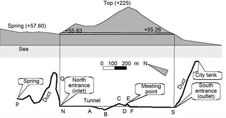
“Three of the greatest works in all Greece were made by [the Samians]. One is a tunnel, under a hill one hundred and fifty fathoms high, carried entirely through the base of the hill, with a mouth at either end. As we see in Figure 6, the length of the cutting is seven furlongs10―the height and width are each eight feet. Along the whole course there is a second cutting, twenty cubits11 deep and three feet broad, whereby water is brought, through pipes, from an abundant source into the city. The architect of this tunnel was Eupalinus, son of Naustrophus, a Megarian.” [15]
The Ancient Greek writer Herodotus states that the City of Samos had a population of 300,000. The city did not have a source of water that could be accessed if the fortified city was placed under siege by enemy attack.
“For these reason, the most famous hydraulic work of ancient Greece was built: The aqueduct of ancient Samos, which was admired both in antiquity (e.g. Herodotus) and in modern times… The most amazing part of the aqueduct is the 1036 m long, roughly 8 feet square, dug from two openings… The construction started in 530BC… and lasted for ten years… The two working groups met in the center of the channel and they had only 60 cm error! The workers had problems because of unstable soil they found and had to make a deviation, but they managed to find again the right way to the opposite working team. The deviation was 200 meters away from a straight line connecting the ends of the tunnel in the heart of the mountain! Around 7000 cubic meter rock were removed from the mountain. [Based upon] the text of Herodotus, Guerin (1856) uncovered the entrance of the aqueduct.” [16]
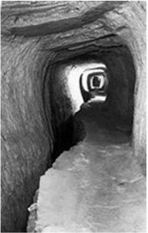
As we see in Figure 7, this Aqueduct system was bored though a mountain then a pipe constructed of 4000 sections was assembled inside the opening to transport the water. This tunnel was utilized for approximately 1000 years, until around 700AD [16] .
Roman Arched Aqueduct Structures (Tunnels and Elevated Channels)
Vestiges of the Roman era waterworks are still visible beneath (and amid) many European cities12 [17] . These visible remnants of the Roman empire would re-inspire the citizens of the western world, as the middle ages transitioned to the renaissance and then into the industrial era. The roman aqueducts are the next Infrastructure project we will focus on. Vestiges of the Roman era waterworks are still visible beneath (and amid) many European cities12 [17] . These visible remnants of the Roman empire would re-inspire the citizens of the western world, as the middle ages transitioned to the renaissance and then into the industrial era. The roman aqueducts are the next Infrastructure project we will focus on.
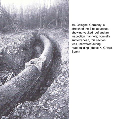
After the completion of the Cloacea, the Romans would move on to their next massive infrastructure undertaking. As we see in Figure 8, they made extensive use of vaulted underground passageways (similar in their structural engineering to the Cloacea) in their system of aqueducts and covered passageways.
The Romans utilized aqueducts to transport water from lakes and mountains that were significant distances away. These aqueduct systems consisted of arched tunnels, channels and elevated channels that were placed atop archways.
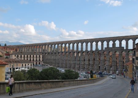
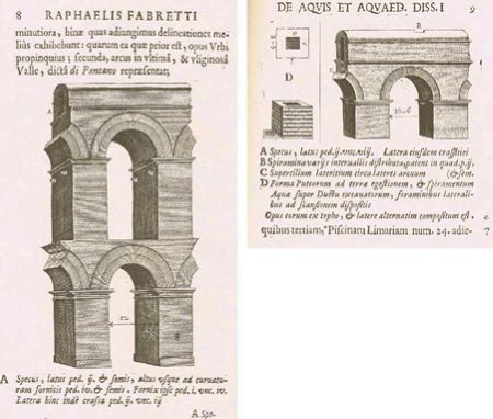
The Romans used vaulted (arched) channels to carry water. As we see in Figure 9 and Figure 10, lofty masonry arches were built by the Romans to carry the Aqueducts over valleys. Whereas, “cut and cover” aqueduct tunnels were extensively used where the waters would best flow underground.
Underground Arched Passageways for Pedestrians and Vehicles – The Roman Cryptoporticus
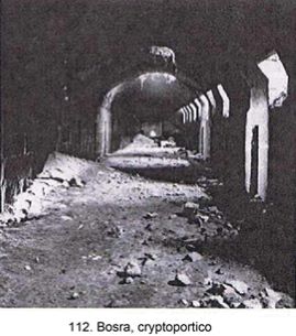
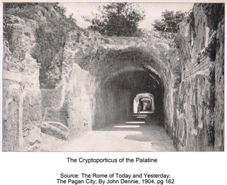
As shown in Figure 11 and Figure 12, from the time period of the Cloaca Maxima, the Romans then developed a residential/commercial use for “cut and cover” vaulted underground passageways: the Cryptoporticus.
“Sometimes connective, functioning as covered passageways, Cryptoporticus are vaulted corridors. Cool and shaded, they are occasionally found alongside streets, sunken below pavement (Bosra [Syria]), but much more often they lined platforms or terraces erected to support major buildings and functioned as ambulatories (Arles [France]; Aeminium [Portugal]; Aosta [France]; Smyrna [Turkey]). The street type is lit by smallish, raking windows set in the haunch of the vault along one side.” [20]
These Cryptoporticus Tunnels are often still in use today as Vehicular highways and/or pedestrian thoroughfares13 [21] .
Fast Forward to the Nineteenth Century
Overview
19th century engineers, when seeking to create great public works, often turned to Roman examples from antiquity for inspiration. First, it is important to note the cultural connection between the Romans, the British and the Americans14. These engineers sought to emulate the types of structures that were successful in withstanding the ravages of time. Structures that continued to serve their intended purpose even after two millennia.
In this section, we will discuss and give examples of three 19th century tunnel construction methods that were widely utilized for underground train routes beneath cities.
1) Building tunnels using explosives;
2) Cut and cover tunnels―utilizing designs similar to Roman vaulted arched construction―used for 19th century aqueducts and the earliest subways (train lines buried for grade separation);
3) The Greathead shield―the earliest tunnel boring machine.
NY & Harlem River RR Tunnels
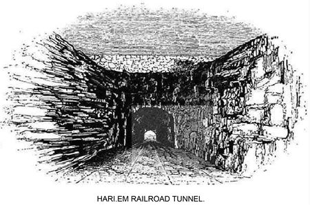
First American Railroad tunnel built using explosives:
Using our proper definition of a railway subway, the second example of such a structure, is the extant NY & Harlem River RR tunnel located on the east side of Manhattan (below what today is Park Avenue) [22] . Shown in Figure 13, this circa 1837 tunnel built by the New York & Harlem RR is still utilized for Rail Service today. It forms the trunk line of the MTA Metro-North Railroad. This line connects Upstate New York with Grand Central Station.
This tunnel was blasted through very tough rock in northern Manhattan. The NY&H RR was the world’s first horse drawn streetcar operation. Built by hand with nothing more than gun powder, the Mt. Prospect tunnel is still in constant use, containing the MTA’s Metro North center express tracks, under Park Avenue between 92nd-94th St.
New York’s Croton Aqueduct
Next, we return to the topic of aqueducts; jumping about 2,000 years from antiquity to 19th century New York. New York City’s (first) Croton Aqueduct was originally designed by Maj. David Bates Douglass circa 1833-5, and later completed by noted engineer John B. Jervis in 1842. The Aqueduct was constructed to address the lack of clean water in 19th century Manhattan (NYC). This lack of water resulted in fires15 and disease outbreaks due to contaminated wells16; epidemics that repeatedly devastated New York City, owing in part to its inadequate water supply and contaminated wells.
“The outbreak [in 1832] highlighted the vulnerabilities of life in overcrowded cities in a time of deplorable sanitation and before medical science recognized the role of germs in disease. Cities were growing faster in population than in understanding what it took to make them fit places to live―an urban problem probably as old as the Sumerians of Mesopotamia” [24] .
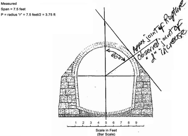
The Croton Aqueduct, this mid-nineteenth century American version of a Roman “underground vaulted passageway” was built to convey water from Westchester County, NY to Manhattan [25] . As we can see in Figure 14, its relatively large cross-sectional design (7.5 ft × 9 ft) is clearly based upon the Roman Cloaca Maxima, the Aqueduct Arcade, or the Cryptoporticus, rather than a typical, small cross section (roughly 2 ft × 4 ft), classical Roman aqueduct “specus”.
What’s an Arch, How Does It Work?
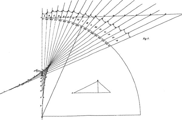
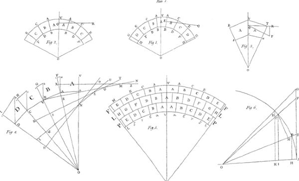
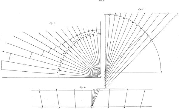
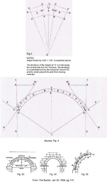
Before we go any further, let’s take a brief look at precisely what an arch is, and how it works. In shape, arches can be circular, elliptical, horse shoe shaped (basket), skew, pointed, corbel- and even perfectly flat. See Figures 15-17 [27] [28] . Referring to the vector diagrams shown in Figure 17(a), Figure 17(b), and Figure 18, here are the rules relating to arches which we distilled from Atwood’s “Dissertation on the Construction of Arches”:
Rule I. “The initial pressure is to the weight of the first section [of the arch], including the weight superincumbent on it [weight of the overburden above the first section of arch] as radius is to twice the sine of the semi angle [half angle] of the middle, or highest wedge [‘keystone’ or ‘crown’ of the arch] or, P=w/(2sin1/2A∘)” [27] .
Rule II. “The horizontal force, which is nearly the same in every part of the arch, is to the weight of the first section [of arch], as radius is to twice the semi angle [half angle] of the first section [of arch] or P′=w/(2tan1/2A∘)” [27] .
Rule III. “The horizontal or lateral force is to the weight of half the arch as radius is to the tangent of the inclination of the abutment to the vertical or Z=P′(secV∘)”.
Rule III. “The horizontal or lateral force is to the weight of half the arch as radius is to the tangent of the inclination of the abutment to the vertical or Z=P′(secV∘)”.
“The horizontal force, or P′; being the weight divided by twice the tangent of the semi angle of the first section, determines the pressure on any abutment of which the inclination to the vertical line is V∘ ; the pressure being P=P′(secV∘)” [27] .
Rule IV. “The horizontal force is to the weight of half the arch as radius is to the tangent of the inclination of the abutment to the vertical or, S=P′(tanV∘)”. The weight of the semi arch [half arch], when adjusted to equilibrium, is found by the fourth rule to be = P′(tanV∘) or the horizontal pressure increased, or diminished, in the proportion of the tangent of the vertical distance of the abutment to radius. From this property, the reason is evident, which causes so great an augmentation in the weights of the sections, when the semi arch [half arch], adjusted to equilibrium, approaches nearly to a quadrant, and which prevents the possibility of effecting this adjustment by direct weight, when the entire arch is a semicircle.” [27]
Rule V. “The weight of the semi arch (half of the arch) is to the pressure on the abutment, as the sine of the said inclination of the abutment is to radius or,
S=Z(sinV∘)
This rule exemplifies the analogy between the entire arch when adjusted to equilibrium, and the wedge. For let the angle between the abutments be 1nade equal to the angle of the wedge, the weight of which is equal to the weight of the arch; and let Z be either of the equal forces, which being applied perpendicular to the sides of the wedge, sustain it in equilibrium: then by the properties of the wedge, the force Z is to half the weight of the wedge as radius is to the sine of the semi angle of the wedge, which is precisely the property of the arch; substituting the angle between the abutments instead of the angle of the wedge, and the pressure on either abutment instead of the force Z.” [27]
Rule VI. “The horizontal force is to the pressure on the abutment as the cosine of the inclination of the abutment is to radius or
P′=Z(cosV∘)
The lateral pressure, or the pressure on the abutment, reduced to an horizontal direction, is nearly the same in all parts of the arc; being to the weight of the first section, as radius is to twice the tangent of the semi angle [half angle] of the wedge.
The force of pressure on the abutment is therefore at every point resolvable into two forces; one of which is perpendicular to the horizon, and is equal to the weight of the semi arch; and the other is a horizontal or lateral force, which is to the weight of the first section, as radius is to twice the tangent of the semi angle of that section.
By these rules, the principal properties of the arch of equilibration [equilibrium] are expressed in simple terms, and are easily applicable to practical cases.” [27]
Calculating the Key Dimensions of a 19th Century Masonry Arch Tunnel
Overview
Now that we have a basic idea of what an arch is, and how it works, let’s look at some simple equations for calculating the key dimensions of a 19th century masonry arch tunnel.
From “A Treatise on Masonry Construction” Baker states that: we glean three important “empirical” formulas for designing a masonry arch, credited to Rankine, and known as “the English Method” [30] . Since the entire concept of the “empirical method” is based upon observation, we’ll pick the formulas that fit best for both the Croton Aqueduct, and the Atlantic Avenue tunnel.
Let’s first take the case of the circa 1842 Croton Aqueduct (NYC) as shown in Figure 14.
Calculating an Arch at the Crown
First, for calculating the thickness of the arch at its highest point, or crown, we’ll use Rankine’s method:
d(crown)=√0.12*r2/8
where: span “s” = 7.5 ft, and the rise “r” = 3.75 ft
d=√0.225
d(crown)=0.47434 ft×12′′/ft=5.69 inches by Rankine’s method.
Since the y axis of a typical period brick laid longitudinally on its edge is about 3-1/2″, two layers of brick arch would be required. In fact, according to a circa 1842 scale drawing, the arch of the Croton Aqueduct is in fact 2 layers of brick thick, and adding 0.5″ for a single cement mortar joint, making the crown of the Croton Aqueduct a total of 7.5″ thick. This matches perfectly with the contemporary scale drawing.
Calculating an Arch at the Springing Line
Next, we must calculate the thickness of the arch at the springing line: to understand this particular equation, one must first appreciate the concept of the “joint of rupture”.
Essentially, this is the joint along any arch that is subjected to the greatest force. Since taking the sum of moments around an arch is somewhat beyond the scope of this article, we’ll use the simple fact that according to Baker, this “joint of rupture” usually forms an angle with the vertical, between 45˚ and 60˚. The “joint of rupture” is also considered to be the point where the arch technically ends, and the abutment theoretically begins. The continuation of the arch from the joint of rupture to the spring line is considered to be a prolongation of the abutment, rather than the arch.
By measuring the original scale drawings of the structures, and taking the joint of rupture to coincide with the joint at which the thickness of the arch begins to increase; on the Croton Aqueduct of 1842, this angle appears to be 60˚ from the vertical. For the Atlantic Avenue tunnel of 1844, this angle appears to be the average of the maxima and minima, as cited by Baker, or 52.5˚ from the vertical.
So, we now have the equation for calculating the thickness of the Croton Aqueduct at its spring-line:
d(spring-line)=d(crown)⋅Secant Θ
where Q = angle made by joint of rupture with the vertical.
Using the trigonometric identity SecantΘ = 1/CosineΘ, our equation can be rewritten as:
d(spring-line)=d(crown)/CosΘ
Plugging in the numbers, we have:
d(spring-line)=7.5′′×(1/Cos60∘)=7.5′′×2=15′
According to the contemporary scale drawing, the Croton is 21″ The additional 6″ of thickness is taken to be the safety margin (40%).
Calculating the Thickness of the Arch’s Abutments at Their Base
Finally, for the thickness of the Croton’s abutments at their base:
d(abutment)=2/3ℎ
where h = clear height of abutment Plugging in the numbers, we have:
d(abutment)=2/3×3.75 ft=2.5 ft thick at the base
Measuring from the contemporary scale drawing, the Croton’s abutments are 2.6ft thick at their base.
The Atlantic Avenue Tunnel
Overview
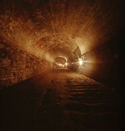
In Brooklyn, circa 1844, the world’s first subway tunnel was constructed. As shown in Figure 19, the ancient concept of the Roman “Underground Passageway” made the technological jump from water tunnels and the cryptoporticus to the urban underground railway…
The Atlantic Avenue Tunnel was built beneath a busy street in the City of Brooklyn, NY17. This tunnel was built for the specific purpose of attaining grade separation for the Long Island Rail Road (LIRR), this structure is therefore officially the world’s first transportation Subway [7] 18.
“The Atlantic Avenue Tunnel is a half-mile long and accommodated two standard gauge railroad tracks. The Atlantic Avenue Tunnel was built in only seven months, using the cut-and-cover method; only hand tools and primitive equipment was utilized in its construction. It was built to provide grade separation for early Long Island Rail Road trains that lacked brakes good enough to operate on city streets. The tunnel was built to attain grade separation for the previously existing LIRR route on the surface of Atlantic Avenue. The tunnel eliminated vehicular and pedestrian traffic conflicts and delays.” [31] [32] [33] .
The 1⁄2 mile arch of the tunnel consists of 5 layers of high quality red burned brick, laid in bond with headers and stretchers, and additional external spandrel material-Mica Schist rubble masonry (Manhattan bedrock) between the joint of rupture and the spring line [32] . These are all laid in a Portland cement/sand mortar. The brick headers interconnect the 5 layers of the brick arch, thereby further strengthening the arch. The tunnel’s abutments (walls) consist of massive Mica Schist rubble masonry, thoroughly grouted with Portland cement/sand mortar.
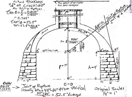
Using Figure 20 lets now apply Rankine’s formulas to the Atlantic Avenue tunnel of 1844.
Calculating an Arch at the Crown
Note that in this particular application of Rankine’s tunnel arch formula, we have doubled the result, as per Baker’s instructions, to account for the fact that the tunnel is built within a sand matrix.
d(crown)=2×(0.12×82/21) ft
d(crown)=2×0.604743 ft
d(crown)=1.209486 ft=14.50 inches by Rankine’s method.
The actual measured thickness at the crown is 20″ (1.60 ft). It’s assumed that the difference of 5.5 inches is a safety factor of 38% at the crown.
Calculating an Arch at the Spring-Line
For calculating the thickness of the Atlantic Avenue tunnel at its spring-line:
d(spring-line)=d(crown)⋅Secant Θ
where Θ = angle made by joint of rupture with the vertical.
Again, using the trigonometric identity SecantΘ = 1/CosineΘ, our equation can be rewritten as:
d(spring-line)=d(crown)/CosΘ
plugging in the numbers, we have:
d(spring-line)=14.50 inches×1/Cos52.5∘
d(spring-line)=23.819 inches, say 24 inches.
The actual as built measured thickness at the spring-line, is 48 inches. It is assumed the 24 inch difference is a safety margin of 100% at the spring- line.
Calculating the volume of masonry building material used in the Atlantic Avenue tunnel.
In mathematical terms, the arch of the tunnel is “an ellipse of the semi major axis (a) and semi minor axis (b)”. Since the ellipse is centered at the origin (0,0), polar equations can be used [35] [36] .
The area of an ellipse centered at (0,0) = πab
Therefore, the general formula for the area of our arch of a single elliptical hemisphere is:
AreaTunnelArch=πab/2
To obtain the area of our arch as shown in Figure 20, we must subtract the area of the inner arch surface (intrado) from the area of the outer arch surface (extrado):
Areaintrado=(3.14×8×10.5)/2=131.88 ft2
Areaextrado=(3.14×9.6×14.5)/2=218.54 ft2
Areatunnelarch=218.54ft2−131.88 ft2=86.66 ft2
Multiplying 86.66 ft2 by 2000 ft, and then dividing by 27 ft3/Yd3, we obtain an arch volume of 6419 Yd3.
However, as we know from our core samples, the arch is not made entirely of brick. The arch is a constant thickness of 20 inches of brick, and supplemented in depth with mica schist rip rap laid in Portland cement mortar, from the joint of rupture to the spring line, as per the cross-sectional view.
This was no doubt done as an economizing measure, as the naturally occurring Mica Schist material was free, except for the cost of cutting in Manhattan and transport to Brooklyn. The brick on the other hand, had to first be manufactured, then purchased, and transported.
Atlantic Avenue Tunnel Number and Volume of Brickwork in the Arch
Let’s now calculate the volume of brick in the arch, and then subtract this volume from the total arch volume:
Areabrickextrado=(3.14×(10.5+1.6)×(8+1.6))/2=182.37 ft2
Area brick arch = Area brick extrado – Area Intrado = 182.37 ft2 – 131.88 ft2 = 50.49 ft2
Volume brick masonry in arch = 50.49 ft2 × 2000 ft = 100,980 ft3/27 = 3740 CY.
Deducting 20% of this volume to account for the Portland cement mortar, we get:
Sample brick taken from the tunnel give us the following dimensions:
Length: 8 inches = 0.666 ft
Height: 2-3/8 inches = 0.1979 ft
Depth: 3-5/8 inches = 0.30208 ft
Therefore, 1 brick = 0.04 ft3, making exactly 25 bricks per cubic foot, exclusive of mortar joints, which are approximately 3/8 inch each.
By deducting 1/5 of the total volume of Brick masonry, to account for the volume of the hydraulic cement mortar per cubic foot, and then dividing the result by 0.04 ft3 per brick, we get a grand total of 2,019,600 bricks in the Arch of the tunnel, exclusive of mortar joints:
100,980 ft3 − (100,980 ft3/5) = 80,784 ft3 Brick = 2992 CY Brick, and 748 CY Portland cement mortar (for brick) in arch.
Finally, 80,784 ft3/0.04 ft3 per Brick = 2,019,600 Bricks in the Tunnel’s arch.
Atlantic Avenue Tunnel―Volume of Stone Rubble in Tunnel Arch
To calculate the volume of stone rubble masonry in the tunnel’s arch:
6419 CY (total arch) − 3740 CY (brick masonry) = 2679 CY Stone Rubble masonry in the arch, of which
2143.2 CY is Mica Schist rubble, and 535.8 CY Portland cement mortar.
Calculating the Thickness of the Base of the Abutment Walls and Volume of Material Used in the Abutments
To calculate the volume of stone rubble masonry in the tunnel’s arch:
6419 CY(total arch) − 3740 CY(brick masonry) = 2679 CY Stone Rubble masonry in the arch, of which 2143.2 CY is Mica Schist rubble, and 535.8 CY Portland cement mortar.
Finally, let’s calculate the thickness of the abutment walls at the base, and then the volume of stone masonry contained in each of the tunnel’s abutments (exclusive of the approach ramps):
d(abutment) = 2/3 h = 2(9 ft)/3 = 6 ft thick at the base of abutment. This precisely matches the as built condition.
AreaperAbutment=(9×4)+(9×2)/2=45 ft2/(9 ft2/Yd2)=5 Yd2
5 YD2×2000 ft/(9 ft2/YD2)=3333 Yd3 per abutment×2=6666 Yd3 total volume. Our ratio of stone to mortar per cubic yard then gives us:
6666 CY−(6666 CY/5)=5332.8 CY Stone Rubble and 1333.2 CY Portland cement mortar total abutments.
Atlantic Avenue Tunnel Total Masonry Work (Excluding Approach Ramps)
Total masonry work excluding approach ramps:
Stone Work:
Abutments: 6666 Yd3
Arch: 2679 Yd3
Sub Total Stone Work: 9345 Yd3
Brick Work (Arch): 3740 Yd3
Atlantic Avenue Tunnel Total Masonry Work (excluding approach ramps): 13,085 CY, of which 10,468 CY is Stone Rubble and Brick, and 2617 CY is Portland cement mortar.
The Murray Hill Tunnel (NY), the World’s Second Subway Tunnel
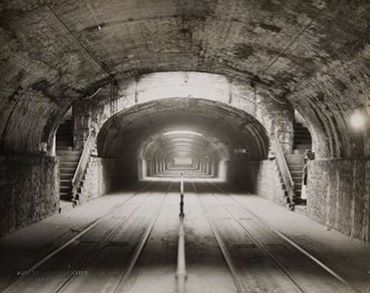
Shown in Figure 21, the second example of a subway (urban underground railway tunnel), is the extant NY & Harlem River RR tunnel located in Park Avenue South between East 33rd Street and Grand Central Terminal (now a vehicular tunnel).
Originally, this tunnel was begun about 1836, only as an open cut through major rock obstruction, called “Murray Hill”, rather than for attaining grade separation. This open cut rock structure was later arched over with brick circa 1850, thereby converting it to an urban grade separated, “cut and cover” tunnel. This tunnel was designed to facilitate and accommodate the real estate development, and the increased volume of pedestrian and horse drawn vehicular traffic, occurring all around it. This tunnel still retains an original streetcar station.
The third railway “subway” constructed19, was London’s [North] Metropolitan Railway, first proposed circa 1853, and completed circa 1863.
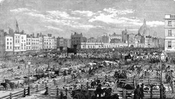
As we can see in Figure 22, London’s first subway was built out of urgent necessity: impassable traffic congestion. It was a 2-1/4 mile short line railroad extension of the Great Western Railway. To attain full grade separation, parts of this route had to be built in both open cut, and in “cut and cover” tunnel. It was part of a main line railway operation, not a separate rapid transit line.
Originally proposed by the City of London’s tenacious Corporation Solicitor, Charles Pearson, Esq., We suspect that he and his adherents were inspired by the tunnels in Brooklyn and Manhattan, which he, or an associate, probably studied on a trip to New York in the late 1840’s or early 1850’s.
This short line railway extension was built using the “cut and cover”, as well as the “open cut” methods, under both streets and private property, to attain grade separation (congested streets) for the Great Western Railway’s new passenger and freight access to the Thames River via downtown London.
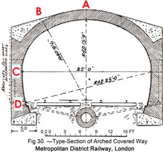
This structure is conceptually similar to the Atlantic Avenue tunnel, as it was also of the brick and stone masonry “cut and cover” type. Structural engineering theory had advanced in the decade since the Atlantic Avenue Tunnel had been constructed. As we can see in Figure 23, the British designers realized that they did not need to utilize expensive 6-foot thick, trapezoidal shaped, abutment walls. The London subway also utilized structural concrete in the arch, and in the abutment foundations. Further, earlier designs (like the Atlantic Avenue Tunnel) directed the forces acting vertically on the arch to the earth outside the tunnel abutment walls. The London underground tunnel was instead designed to vector the vertical forces acting upon the arch to the earth directly underneath the tunnel.
This structure is Writing of London’s original Metropolitan Railway line, the 1911 Encyclopedia Britannica [38] , states: Wherever possible the lines were constructed in open cutting… where this was not possible, they were built by a method suggestively called “cut and cover”. This first line of the London Underground is essentially the Atlantic Avenue tunnel, lengthened accordingly to suit its particular route.
As to its original purpose, London’s Metropolitan Railway line was in fact part of a much larger system of railways (as was the Atlantic Avenue tunnel/LIRR). London’s Metropolitan Railway was also built to provide rail freight service to the massive Smithfield cattle stockyards and meatpacking facilities, pictured below. The original function of this London “underground” line was “mixed use” (i.e., passenger and freight):
“The main purpose of the Metropolitan Railway, as is well known, is the making [of] a line from the Great Western at Paddington to a point on the eastern side of Victoria Street (Holborn)…”
Slaughter goes on to write: “the… Metropolitan Railway will be thus placed in direct railway communication not only with Dover and the Continent, but also with the southern portions and suburbs of the metropolis [London]”, and further, “Arrangements have been made by this Company [Metropolitan Railway], and the Great Western Railway Company, with the Corporation [City of London] for the use of the ground under the [Smithfield] market for the purposes of a goods’ station” [40] .
Railway Intelligence, by Mihill Slaughter (1860) [40] , gives us a detailed, firsthand account, as to the origins and purposes, of the first of the London Underground lines:
“The main purpose of the Metropolitan Railway, as is well known, is the making a line from the Great Western at Paddington to a point on the eastern side of Victoria Street (Holborn). Other objects more or less tending to the advantage of the Company have since been added, and these may be best explained in the following summary…”
The Corporation of London have obtained the sanction of Parliament to establish extensive markets in Smithfield for the sale of meat and provisions, and to afford to Railway Companies facilities there, not only for traffic for the purposes of the markets, but also for receiving and delivering goods for the general trade of the city and the central districts of the metropolis.
An Act has been passed for a short line to connect the railway with the new markets, and with the large and convenient railway station which will there be formed.
Arrangements have been made by this Company, and the Great Western Railway Company, with the Corporation for the use of the ground under the market for the purposes of a goods’ station [40] .
It is interesting that the London underground railway project was from the outset, an infrastructure project designed not only to improve urban mobility, but also to have an economic impact on the surrounding neighborhood. It is also interesting that we normally view a subway system as a system designed exclusively to move people from place to place. However, it is clear from the description above that the system was designed to move both passengers and freight (like a conventional railway line).20
Epilogue: Greathead Shield & the Deep Tubes
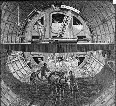
The next major innovation in subway construction was: The “deep tubes” built for the London Underground, circa 1886, using the Greathead Shield (a very early form of a tunnel boring machine).
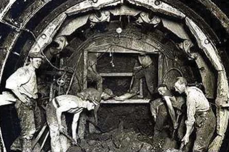
“The City & South London Railway is the world’s first deep-level underground (tube) passenger railway. It is also the first urban electric traction railway in England, and is now part of the Northern Line in the London Underground network. The tunnel for City & South London Railway was the first railway tunnel to be excavated using a tunneling shield rather than the “cut and cover” method used elsewhere. The shield was designed by South African engineer James Henry Greathead. As we can see in Figure 24 and Figure 25, it was cylindrical and had steel blades that were forced into the soil by hydraulic rams operating at a pressure of 1575 tonnes per square meter (2240 psi)” [41] A completed section of tunnel is shown in Figure 26. Note the bolted together cast iron tunnel ring segments.
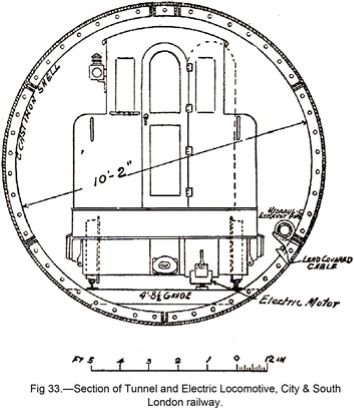
We end with this paper with the Greathead shield, one of the first of new pioneering tunnel construction technologies, methodologies and materials that would depart from tunneling methods and materials used since antiquity. These new technologies would facilitate the construction urban rail systems in New York, London, and in cities throughout the world, in the late 19th and early 20th centuries. Much can be written regarding the subway innovations that happened during this period. We will cover these in detail in a subsequent paper.
Conclusions
This paper traces the evolution of tunnel engineering from Ancient Mesopotamia and the Middle East though Greece and Rome. In the 19th century, New York, ancient roman tunneling technology was rediscovered and re-utilized for aqueducts like the Croton. Moreover, the Roman style of vaulted arch tunnel, which they utilized for pathways and roads (the Cryptoporticus), was repurposed in the 19th century Brooklyn and London for industrial age transportation applications. The first subway tunnels were essentially Cryptoporticus with railroad tracks.
In 1844, the world’s first Subway (aka. Tube, Metro, etc.) tunnel opened in Brooklyn. In many regards, the Atlantic Ave. Tunnel in Brooklyn, and the North Metropolitan Railway tunnel (the first London Tube tunnel) were enlarged versions of Roman Tunnels.
This emulation of the Romans in the first Subway tunnels made sense. When you seek to build something that has never been built before, it is often wise to adopt an architectural solution and structural engineering system from something similar that has withstood the ravages of time. In this paper, we sought to elucidate the engineer principles and mathematical formulas that these 19th century engineers utilized for vaulted arched aqueducts and subway tunnels.
An interesting side-note is that in addition to railway tunnels, the Romans were also emulated through the adoption of the Standard gauge railroad track, which is used throughout the NYC subway system. Moreover, Standard gauge is the most commonly used gauge (spacing between track) used by railroads throughout the contemporary world [24] .
Appendix
Endnotes
- “First recorded in 1820-30; sub- + way1” [1] .
- In addition to the term subway’s most prevalent use in the NY area, as a label we affix to our urban rail transit system, the term “subway” can also refer to any underground passageway, i.e., things such as an underground: pipe gallery, utility area or water conduit. For example, in Manhattan, New York “The Empire City Subway” is not a railway―it is underground vaulting built to contain telephone company cables [2] .
- “The oldest [written] reference concerning the existence of a drainage system known today so far has been discovered on an older sealing inscription. It was referred to as the construction of a palace and the drainage system of a warehouse. Other information concerning drainage systems in Mesopotamian cities is much younger.” [4]
- Most dimensions in this paper, and the historical sources cited, are in feet and inches. However, all of Merckel’s measurements are in Meters (1 Meter = 3.28 feet). Further, his particular use of a “comma” when citing dimensions, is equivalent to our decimal point.
- “The brick is quadrangular but not wedge-shaped. The central space… is filled up with brick, laid down in linear length.”
- Cut and cover construction refers to trench excavation, then tunnel construction, then road restoration. This technique will be detailed later in this paper.
- “The exact survey of the Roman sewer network is due to the Italian Engineer Pietro. Due to him, the Cloaca Maxima consists of big Gabine ashlars stones with the following measurements: Length: 2, 50 meters, Height: 0, 80 meters, width: 1, 00 meters. The stones had been connected without grout and mortar. The walls consist of 3 – 4 ashlars layers. A semi-circular shaped arch is based upon them. This barrel vault has 7 to 9 ashlars layers formed by accurately arranged key stones. The river bed is paved with polygonal lava stones. The figures nos. 170 – 172 are illuminating the cross section resp. The longitudinal section of the Cloaca segment (up to the Forum Augustum) that was discovered in 1889. Figure No. 173 shows the cross section of Point No. 2 from the fig. No. 169 site map. Here, as it can be seen in figure No. 173, only two original ashlars stones still exist. Above them, there is a semi-circular vault based upon brick layers. The width of the channel is variable, depending upon the hydraulic gradient conditions. Towards the estuary mouth, the cross section widens. This is an appropriate constellation because the quantity of water that has to be drained is also increasing. The air shafts in fig. 176 & 178 are from a later date. Just after the Cloaca has passed the Janus quadrifons, the same covering vault of key stones ends into a perpendicular front (fig. 177). The adjacent 39 meters show a brick vault. Fig. 179 reproduces the longitudinal section of the Cloaca; fig. 180 is the view of the sewer at Point No. 10.” [4]
- The work was begun by the first Tarquin [Priscus]; it seems to have been in a degree suspended in the reign of Servius Tullius; and it was completed by Tarquin the Proud [Tarquin Superbus]” [8] .
- Compare this to Walt Whitman’s writing on the Atlantic Avenue tunnel, some 2300 years later: “A Passage of Solemnity and Darkness” [Whitman, 1963 #1] [14] .
- Furlongs: “a unit of distance, equal to 220 yards (201 meters) or 1/8 mile (0.2 km)” [1] .
- Cubit: “an ancient linear unit based on the length of the forearm, from elbow to the tip of the middle finger, usually from 17 to 21 inches (43 to 53 cm). the other side of a mountain there were mountain streams that could supply the town with a source of water [15] [16] .
- “In Paris, fragments of the former drainpipes from Roman Times are still preserved upon the isle of Notre Dame. The height of these pipes is 0, 60 meters, the width 0, 50 meters. Remnants of Roman drainpipes have been found in Cologne and in Treves, Germany. Fig. 181 shows the cross section of the channel which was exposed in the neighborhood of Alteburg in Cologne. Interestingly enough are the applied forms of the cross section as well as the embedding of the pipe in blue colored clay.” [4]
- “Flaminia, Via, an ancient high road of Italy, constructed by C. Flaminius during his censorship (220B.C.). It led from Rome to Ariminum, and was the most important route to the north… Vespasian constructed a new tunnel through the pass of Intercisa, modern Furlo, in A.D. 77” [23] .
- England was colonized by Rome. Then America was colonized by Britain. Therefore, what would become the United States began as a colony, of a colony of Rome. Therefore, when 19th century engineers were emulating and appropriating Roman vaulted tunnel technology, they were drawing upon what they viewed as the historical roots of their own culture.
- Fires also ravaged NYC during this era, often burning beyond control [24] . These hard to extinguish fires were partly due to lack of ample pressurized water.
- “It was 1883 before the bacterium Vibrio cholerae was discovered to be the agent causing the gastrointestinal disease. But a turning point in prevention came in 1854, when a London physician, Dr. John Snow, established the connection between contaminated water and cholera. Dr. Snow tested the idea by plotting cholera cases on a map of Soho. This showed that most of the victims drew their water from a public pump on Broad (now Broadwick) Street. An infected baby’s diapers had been dumped into a cesspool near the well. A recent book, ‘Ghost Map’ by Steven Johnson, recounts the discovery.” [26]
- Brooklyn did not become part of NYC until 1898-a half-century after the Atlantic Avenue Tunnel was built.
- See the following link for contemporary historical documentation:
http://brooklynrail.net/images/aa_tunnel/new_research/oct_09/events_leading_to_tunnel_creation.pdf - The Murray Hill Tunnel in Manhattan, we consider to be the second Subway tunnel, and the London tunnel is the third.
- This station resembles the original LIRR passenger/freight terminal at Atlantic Avenue & Columbia Street. This station was rebuilt (when the tunnel opened) in 1844, a decade prior to the first London Underground line. Also, another passenger/freight terminal station later arose on that same LIRR line at Flatbush & Atlantic Ave in Brooklyn, NY.
References
- Subway/Define Subway at Dictionary (2017)
- Empire City Subway. (2017)
- Sewer History Photos and Graphics (2017)
- Merckel, C. (1899) The Engineer Technique in Antiquity. Springer, Berlin, 454-465.
- Angelakis, A.N., Chiotis, E., Eslamian, S. and Weingartner, H. (2016) Underground Aqueducts Handbook. CRC Press, 367.
- How Did King David Conquer Jerusalem (2017)
- Diamond, R.S. (2015) The Expanded Red Hook Streetcar Project a Cure for Transportation Deserts. Lulu Press, p. 7.
- Dennie, J. (1904) Rome Today and Yesterday. The Pagan City, G.P. Putnam’s Sons, p. 47-48.
- Ancient Bible and Book of Mormon Cities Part IV (2017)
- Rome Is Still Technically Using One of the First Sewer Systems in the World (2017)
- Vitruvius and Morgan, M.H. (1914) The Ten Books on Architecture. Harvard University Press, Book VIII, Chapter VI.
- Baedeker, K. (1886) Italy Handbook for Travelers. K. Baedeker, Ninth Revised Edition, p. 245.
- http://jenkinsancienthistory.weebly.com/uploads/2/6/9/9/26990891/8908790.jpg
- Whitman, W. (1963) Walt Whitman’s New York from Manhattan to Montauk. Macmillan, p. 159.
- The History of Herodotus by Herodotus, 440 BCE (2017)
- Lahanas, M. (2017) The Eupalinos Tunnel of Samos.
- Hodge, T. (2002) Roman Aqueduct & Water Supply. Duckworth, p. 347-348.
- https://brandondarnell.files.wordpress.com/2012/11/segovia-roman-aqueduct-01.jpg
- Fabretti , R. (1680) De Aqus et Aquaeductibus Veteris Romae. 3rd Edition, Alan Wofsy Fine Arts, p. 8-9.
- MacDonald, W. (1986) The Architecture of the Roman Empire. Volume II, an Urban Appraisal, Yale University Press, p. 117, 118.
- Picture of New York. (1846) Homans & Ellis, p. 86-89, 160-161.
- Lacus Curtius · Via Flaminia. (1911) Encyclopaedia Britannica.
- Wilford, J.N. (2008) Cholera Epidemic in New York City in 1832.
- Jervis, J. (1842) Description of the Croton Aqueduct Croton Aqueduct. Slam and Guion, p. 5.
- Johnson, S. (2006) The Ghost Map: The Story of London’s Most Terrifying Epidemic and How It Changed Science, Cities, and the Modern World.
- Atwood, G. (1801) A Dissertation on the Construction of Arches. Bulmer and Company, p. 1, 19, 20.
- The Builder. Volume 86, p. 113.
- Tower, F.B. (1843) Illustrations of the Croton Aqueduct. Wiley & Putnam, p. 85.
- Baker, I.O. (1909) A Treatise on Masonry Construction. J. Wiley & Son, p. 641-646.
- Diamond, R. and Kassel, B. (2009) The Confluence of Four Events That Led to the Creation of the Atlantic Avenue Tunnel. The World’s First Subway.
- The Atlantic Avenue Tunnel by Robert Diamond and Vincent R. Richardi, P.E. (1983) The Municipal Engineers Journal, Fall Issue, Vol. 69, The Municipal Engineers of the City of New York, p. 5, 11. Diamond, R. and Kassel, B. (2011)
- NYC Dept. of Highways, and Brooklyn Borough President’s Topographical Bureau. (1916)
- Liu, J. and Spiegal, M. (1999) Schaum’s Outline Mathematical Tables and Formulae. 2nd Edition, McGraw Hill Companies, p. 15.
- CRC Standard Mathematical Tables and Formulae. (2003) 31st Edition, CRC Press, p. 330-331.
- New York City Municipal Archives Photo, Murray Hill Tunnel, circa 1923.
- Encyclopedia Britannica. 11th Edition, Vol. 22, The Encyclopedia Britannica Company, p. 856.
- Porter, R. (2001) London, a Social History. New Edition, Penguin, p. 193.
- Slaughter, M. (1860) Railway Intelligence. No. XI, Dec 31, p. 114-115.
- Engineering Timelines—City & South London Railway. (2017)
- Mayo, R. (1941) Practical Tunnel Driving. McGraw Hill.
Originally published by Journal of Transportation Technologies 8:1 (January 2018), DOI:10.4236/jtts.2018.81002, under the terms of a Creative Commons Attribution 4.0 International license.


